
|
|
|
|
billcoe_
Jan 10, 2008, 8:51 PM
Post #1 of 29
(24212 views)
Shortcut
Registered: Jun 30, 2002
Posts: 4694
|
This needs a new thread so we can all compare notes. For you people who have built, or are going to build testing rigs, what parts did you use, where did you get them and what did it cost? (I am trying to shortcut the learning curve some of you may have already paid for, but I suspect that lots of other climbers would jump on this if the info was available).
It would be nice to have a device to pull test Aliens, AND be portable enough to go out to a remote virgin wall (or 5) that has unusual stone composition to test various bolting methods for comparison sake before the first bolt goes in.
Post up boyz!
From the other thread:
adatesman wrote: Funny this thread should come up on the front page again.... Not to take anything away from the OP, but I just finished building my own pull testing rig and was wondering what to do with it. Tsuli- What kind of equipment do you have for testing / what kind of tests do you have in mind? I did mine on the cheap for a project I'm working on, so only a 5" stroke x 10 ton hydraulic pullback ram for static testing. But rather than using rated cord as a fuse to ballpark breaking strengths I got my hands on a 10,000 pound s-beam load cell and a Daytronic 4077 strain gage indicator, which should allow me to measure both static and dynamic forces up to ~44kN. The 4077 has an actual analog channel, so capturing true peak load values in dynamic tests shouldn't be a problem (unlike with most other indicators where you're limited by the scan frequency). But I only dabble in these sorts of things, so I'm curious what your take on this sort of this is since you probably know much more about it than I do. At the moment I've just been playing with pull testing cams on the test jig, but if I can figure an easy, packable AC power source for the 4077 (couldn't find the DC version cheap) packing it to the crag for real world testing of most anything is certainly possible. Feel free to PM me and we'll compare notes. -a. |
|
|
|
|
healyje
Jan 10, 2008, 9:26 PM
Post #2 of 29
(24195 views)
Shortcut
Registered: Aug 22, 2004
Posts: 4204
|
http://cgi.ebay.com/...=cross_promot_widget
http://cgi.ebay.com/...p1638Q2em118Q2el1247
Bill, probably you could do it with these two, a compressor, and some sort of strong ass frame for them. Those, and whatever jigs for holding and clamping on to gear. Don't know how fast or slow that rams works - I would guess you'd want it to go slower than faster. A hydraulic ram with a hose to a hand pump might also be desirable, but I've never used either type so can't say one way or the other.
|
|
|
|
|
adatesman
Feb 11, 2008, 3:12 AM
Post #3 of 29
(24045 views)
Shortcut
Registered: Jul 13, 2005
Posts: 3479
|
|
|
|
|
|
russwalling
Feb 11, 2008, 4:59 AM
Post #4 of 29
(24011 views)
Shortcut
Registered: Jun 12, 2002
Posts: 239
|
For portable: dynamometer and a come-along. Gets scary at about 3000 - 4000lbs.
For cheap shop: dynamometer and an engine hoist/cherry picker thingy. Attach a bar across the "legs" of the contraption and use this as your bottom fixed point. Plenty of travel in the "crane" part to test all sorts of stuff. Total outlay will be about $200 max.
|
|
|
|
|
adatesman
Feb 11, 2008, 3:12 PM
Post #5 of 29
(23971 views)
Shortcut
Registered: Jul 13, 2005
Posts: 3479
|
|
|
|
|
|
russwalling
Feb 11, 2008, 4:52 PM
Post #6 of 29
(23947 views)
Shortcut
Registered: Jun 12, 2002
Posts: 239
|
Keep looking. The engine hoist I got is a 2 ton, which is 4000 lbs. Which means I can take it to 5000 with only a few worries. $99.00 on sale.
Dynamometers show up on ebay all the time for way cheaper than that. I got a 5000 lb one for 75.00. At the time I was looking, I would bid on them and my max bid was something like $85.00. Most were selling at about $100 - $150. Too much for me!
I agree about the hydraulics keeping your eyes in your head. But... for cheap and portable, eyes and lips might be lost.
quick ebay search has some in the $125/$150 buy it now range and $25 one.
http://cgi.ebay.com/Dillon-Crane-Dynamometer-Hanging-Scale_W0QQitemZ130195972597QQihZ003QQcategoryZ11814QQssPageNameZWDVWQQrdZ1QQcmdZViewItem
http://cgi.ebay.com/Dillon-Dynamometer-Suspension-Scale-by-Brechbuhler_W0QQitemZ300197493332QQihZ020QQcategoryZ4115QQssPageNameZWDVWQQrdZ1QQcmdZViewItem
Search on "crane scale" too...
Good luck!
|
|
|
|
|
adatesman
Jun 10, 2008, 1:56 AM
Post #7 of 29
(23548 views)
Shortcut
Registered: Jul 13, 2005
Posts: 3479
|
|
|
|
|
|
spikeddem
Jun 30, 2008, 6:15 AM
Post #8 of 29
(23233 views)
Shortcut
Registered: Aug 27, 2007
Posts: 6319
|
What's the difference between a strain gage indicator, a load cell, and a dynamometer?
For the portable system using a come-along, to what do you normally anchor the come-along?
http://cgi.ebay.com/...QQrdZ1QQcmdZViewItem
That come along says its rated to four tons, does that mean I can generate up to four tons (safely) on it with just my hand? What can I legally attach it to that will take 8000 lbs. of force?
I saw the note about safety concerns at the 3000-4000 lbs. for the come-along systems you mentioned. Is that still a worry even on a 4 ton come-along?
Thanks!!
Edit: Could I just have a friend weld a steel frame together for it? If I were testing something, and it broke at 2500 or 3200 lbs. of force, would the cable and hooks go flying? Seems like it wouldn't be too difficult to build some kind of container to protect against that . . . but I am not a guy with much mechanical background (had to look up even "engine hoist," haha). Then again, I've never seen what steel hooks and cables act like when they're released from a few thousand lbs of pressure. Wow, my edit is longer than my original message.
(This post was edited by spikeddem on Jun 30, 2008, 6:27 AM)
|
|
|
|
|
JimTitt
Aug 8, 2008, 5:42 PM
Post #9 of 29
(22269 views)
Shortcut
Registered: Aug 7, 2008
Posts: 1002
|
This sort of come-along is what I use for testing stakes and stuff like that.
Even though it said 4 tons on the box neither I or my brother could get over 1100 kg using the wire double purchased. A quick calculation showed that one needs to pull 266kg on the handle to get 4000kg pull. I made an extension handle which gets me up to around 2500kg.
I always use restraint leashes (old climbing rope) on its parts as well as the tested object. Bits really fly sometimes, especially the load cell which weighs 10kg.
I later discovered that this type of come-along are rated for the weight of a ROLLING load.
Jim
|
|
|
|
|
jfield
Jun 17, 2009, 9:16 PM
Post #10 of 29
(19474 views)
Shortcut
Registered: Apr 26, 2005
Posts: 5
|
Aric,
I have pondered the issue of dynamic load testing a little(and I even built a dynamic load test meter and gage for Metolius), and my conclusion is that conventional strain gages are probably not reliable for accurate dynamic load testing. Capcitance gages based on a high frequency (~100 Mhz) carrier should be used instead.
I assume that the testing jig is small enough that wave transit times can be safely neglected. I also assume that the manufacturers of quality strain gages use materials not subject to significant piezoelectric effects(electric field coupling to mechanical strain) and that this dynamic problem can be safely ignored. In any event, it is likely that the RC time constants of such effects would be sub microsecond and therefore not of importance to millisecond measurements that we are interested in.
The problem I am concerned with has to do with the temperature change of materials on expansion. The strain gage block is in thermodynamic equilibrium between the applied mechanical stresses and the internal thermal pressure of the gage block's lattice. Due to the expansion or contraction of the gage block, mechanical work is done on the thermal pressure. Therefore, the temperature changes. Now, the temperature change is relatively slight, but the electronic strain gage is measuring a similarly slight change in resistance using a bridge circuit to effectively amplify the slight resistance change. A well designed bridge circuit is designed to be temperature compensated so as to cancel the effect of changing temperature. Unfortunately, this temperature compensation is only going to work to the extent that the entire gage bridge circuit changes in overall temperature. A gradient in temperature across the gage will render the compensation useless.
Now, when you consider that the gage material is different than the strain block and that the stresses in the block have some kind of complicated shape dependence, we see that the sudden application of strain will set in motion rapid fluxes of heat in the vicinity of the gage itself. The thermal equilibration time for a plastic film against aluminum is probably in the low millisecond to high microsecond range. Meanwhile the thermal equilibration in an aluminum gage block probably has many different decay constants for the different excited thermal modes varying from hundredths of a second to perhaps a second or so. Therefore, during these fast intervals, unless you know and have carefully studied the design of the gage block and the internal stresses and thermal fluxes, I do not think you can count on thermal compensation to cancel the (induced) temperature effect errors. As I mentioned above, since the termperature changes are of similar fractional scale as the resistance changes(both being proportional to V/V0) it appears to me that dynamic measurements are subject to a potentially first order error in scale factor - and therefore of uncertain accuracy. From a practical perspective, an error of even +/-20% would render measurements against specification standards(like biner strengths) of relatively little value.
Of course, with capacitance or other accurate dynamic gage, these effects could be tested and (if necessary) calibrated out of the strain gage device - but I don't know of devices that come with this calibration out of the box - perhaps they exist. 
cheers,
John
|
|
|
|
|
boku
Jun 17, 2009, 9:57 PM
Post #11 of 29
(19457 views)
Shortcut
Registered: Jun 11, 2004
Posts: 278
|
adatesman wrote: ...2500 PSI working pressure with a 1-1/2" shaft works out to ~20kN. Did I mention it has 36" of stroke?...
Hang on there a sec, I don't think that analysis captures the actual pulling capacity. I went through this for the original Break-O-Tron, where I used a pressure gauge to measure force (workable, but troublesome), so I think I have a handle on this.
The specs on that Northern Tool site show a rod diameter of 1.5" and a bore diameter of 2.5". To find the effective pullback force at 2500 PSI, I think you'd subtract the cross-sectional area of the rod from the cross sectional area of the bore, and then multiply the remaining area by the maximum pressure rating.
A=pi*r^2
A_rod=pi*(1.5/2)^2
=1.767in^2
A_bore=pi*(2.5/2)^2
=4.909in^2
A_effective=A_bore-A_rod
=4.909in^2 - 1.767in^2
=3.142in^2
Force_max=A_effective*pressure_max
=3.142in^2*2500lbs/in^2
=7855 lbs (kewl how the in^2 cancels out)
=34.9 kN ('biner breakin' bad!)
Thanks, Bob "BoKu" K.
|
|
|
|
|
sixleggedinsect
Jun 20, 2009, 5:11 AM
Post #12 of 29
(19343 views)
Shortcut
Registered: Apr 14, 2004
Posts: 385
|
for folks who were looking for the ultimate in portability and minimizing investment, the 'fuse' method is still an option. obviously, there are all kinds of problems with it, but it should get you in the ballpark if you do the knot math, pull a few, and give yourself a margin.
i know this is not a hot/current topic, but if folks are ever clicking through this in the future, a possibly useful link is this table of accessory cord strengths
http://electricant.net/...c_cord_strengths.htm
and this table of tech cords and other misc climb-spec cordage
http://electricant.net/...ch_cord_strength.htm
|
|
|
|
|
hafilax
Jun 20, 2009, 7:33 PM
Post #13 of 29
(19296 views)
Shortcut
Registered: Dec 12, 2007
Posts: 3025
|
I thought a piezoelectric transducer might do the trick but my search only turned up devices that go to a max of 500lbs (2.2kN) in tension but 5000lbs (22kN) in pressure. Too bad. They are designed for this type of measurement as far as I could tell.
|
|
|
|
|
jt512
Jun 20, 2009, 11:27 PM
Post #14 of 29
(19269 views)
Shortcut
Registered: Apr 12, 2001
Posts: 21904
|
jfield wrote: Aric, I have pondered the issue of dynamic load testing a little(and I even built a dynamic load test meter and gage for Metolius), and my conclusion is that conventional strain gages are probably not reliable for accurate dynamic load testing. Capcitance gages based on a high frequency (~100 Mhz) carrier should be used instead. I assume that the testing jig is small enough that wave transit times can be safely neglected. I also assume that the manufacturers of quality strain gages use materials not subject to significant piezoelectric effects(electric field coupling to mechanical strain) and that this dynamic problem can be safely ignored. In any event, it is likely that the RC time constants of such effects would be sub microsecond and therefore not of importance to millisecond measurements that we are interested in. The problem I am concerned with has to do with the temperature change of materials on expansion. The strain gage block is in thermodynamic equilibrium between the applied mechanical stresses and the internal thermal pressure of the gage block's lattice. Due to the expansion or contraction of the gage block, mechanical work is done on the thermal pressure. Therefore, the temperature changes. Now, the temperature change is relatively slight, but the electronic strain gage is measuring a similarly slight change in resistance using a bridge circuit to effectively amplify the slight resistance change. A well designed bridge circuit is designed to be temperature compensated so as to cancel the effect of changing temperature. Unfortunately, this temperature compensation is only going to work to the extent that the entire gage bridge circuit changes in overall temperature. A gradient in temperature across the gage will render the compensation useless. Now, when you consider that the gage material is different than the strain block and that the stresses in the block have some kind of complicated shape dependence, we see that the sudden application of strain will set in motion rapid fluxes of heat in the vicinity of the gage itself. The thermal equilibration time for a plastic film against aluminum is probably in the low millisecond to high microsecond range. Meanwhile the thermal equilibration in an aluminum gage block probably has many different decay constants for the different excited thermal modes varying from hundredths of a second to perhaps a second or so. Therefore, during these fast intervals, unless you know and have carefully studied the design of the gage block and the internal stresses and thermal fluxes, I do not think you can count on thermal compensation to cancel the (induced) temperature effect errors. As I mentioned above, since the termperature changes are of similar fractional scale as the resistance changes(both being proportional to V/V0) it appears to me that dynamic measurements are subject to a potentially first order error in scale factor - and therefore of uncertain accuracy. From a practical perspective, an error of even +/-20% would render measurements against specification standards(like biner strengths) of relatively little value.
Yeah, yeah. Tell us something we don't know!
Jay
|
|
|
|
|
rschap
Dec 14, 2009, 1:53 AM
Post #15 of 29
(18508 views)
Shortcut
Registered: Sep 30, 2005
Posts: 592
|
Reviving an old thread, again
I read through this thread and unfortunately a lot of the links are to EBay auctions that have ended. Im looking to build a cheap tester that I can compare different designs with. Im not too concerned with the accuracy that Arics tester gets but I would like a good idea of what each item will hold. I think you covered the jig and puller well enough in this thread (besides I can figure that part out for myself) but the load testers seemed vague without the links working. It seems to me that there are three or four different types (what I gathered from this thread) strain gage indicator, a load cell, a dynamometer, and digital crane scale. When I do searches for these things it comes up with all kinds of stuff. To help narrow the search down is there different key words you use or do you just fish through each time. Also what is the minimum poundage you would suggest? And just to see how much info I can pump out of you guys, what options would be necessary? I imagine something that tells the peak holding power but is there anything else?
Randall
|
|
|
|
|
USnavy
Dec 14, 2009, 5:14 AM
Post #16 of 29
(18457 views)
Shortcut
Registered: Nov 6, 2007
Posts: 2667
|
rschap wrote: Reviving an old thread, again
I read through this thread and unfortunately a lot of the links are to EBay auctions that have ended. Im looking to build a cheap tester that I can compare different designs with. Im not too concerned with the accuracy that Arics tester gets but I would like a good idea of what each item will hold. I think you covered the jig and puller well enough in this thread (besides I can figure that part out for myself) but the load testers seemed vague without the links working. It seems to me that there are three or four different types (what I gathered from this thread) strain gage indicator, a load cell, a dynamometer, and digital crane scale. When I do searches for these things it comes up with all kinds of stuff. To help narrow the search down is there different key words you use or do you just fish through each time. Also what is the minimum poundage you would suggest? And just to see how much info I can pump out of you guys, what options would be necessary? I imagine something that tells the peak holding power but is there anything else? Randall
For bolts, 40 kN, for anything else, 30 kN. I have almost maxed my 10klbs. tester out pulling glue in bolts. However I almost never get above 6000 lbs testing anything else.
|
|
|
|
|
|
|
|
adatesman
Jan 3, 2010, 4:31 PM
Post #18 of 29
(18148 views)
Shortcut
Registered: Jul 13, 2005
Posts: 3479
|
|
|
|
|
|
rschap
Jan 3, 2010, 5:40 PM
Post #19 of 29
(18116 views)
Shortcut
Registered: Sep 30, 2005
Posts: 592
|
Cool, thanks a lot Aric.
|
|
|
|
|
japhyr
May 23, 2010, 11:27 PM
Post #20 of 29
(17402 views)
Shortcut
Registered: Dec 27, 2003
Posts: 77
|
Can someone familiar with this thread offer me a little advice on a reasonable setup to aim for?
I am a high school teacher, and I would like to do some dynamic load testing of different systems with students. For example, I would like to hang a load cell from the ceiling, and drop weights from the cell. I would like students to examine the effect of dropping distance on the peak force, and ideally our setup would generate so many force readings per second, so we could examine how the energy is absorbed by the system. We do NOT want to test to failure, so we don't need a high-capacity setup. Dropping a 5# weight from various heights, and examining the ratio of forces generated to the weight dropped, would do what we need.
This kind of setup would also be useful for some static testing, such as examining how an equalized anchor shares a load among individual anchors.
I have a background in physics, but I am getting lost in all the transducers, s-beam and canister load cells, and readouts I have been looking at. Can someone suggest a simple load cell to look at, and suggest what else I need to capture the data that the load cell would output?
Thank you.
Eric
|
|
|
|
|
USnavy
May 24, 2010, 2:25 AM
Post #21 of 29
(17385 views)
Shortcut
Registered: Nov 6, 2007
Posts: 2667
|
japhyr wrote: Can someone familiar with this thread offer me a little advice on a reasonable setup to aim for? I am a high school teacher, and I would like to do some dynamic load testing of different systems with students. For example, I would like to hang a load cell from the ceiling, and drop weights from the cell. I would like students to examine the effect of dropping distance on the peak force, and ideally our setup would generate so many force readings per second, so we could examine how the energy is absorbed by the system. We do NOT want to test to failure, so we don't need a high-capacity setup. Dropping a 5# weight from various heights, and examining the ratio of forces generated to the weight dropped, would do what we need. This kind of setup would also be useful for some static testing, such as examining how an equalized anchor shares a load among individual anchors. I have a background in physics, but I am getting lost in all the transducers, s-beam and canister load cells, and readouts I have been looking at. Can someone suggest a simple load cell to look at, and suggest what else I need to capture the data that the load cell would output? Thank you. Eric
You would need a load cell and a dynamometer with a very high scan rate and peak hold function to capture the peak load. Actually having one that can provide a manual analog waveform output to analyze the peak voltage would be best. Adatesman can hook you up with info on the meter he uses. Also an analog dynamometer with a needle may work as well.
(This post was edited by USnavy on May 24, 2010, 2:26 AM)
|
|
|
|
|
gmggg
May 25, 2010, 8:26 PM
Post #22 of 29
(16927 views)
Shortcut
Registered: Jun 25, 2009
Posts: 2099
|
japhyr wrote: Can someone familiar with this thread offer me a little advice on a reasonable setup to aim for? I am a high school teacher, and I would like to do some dynamic load testing of different systems with students. For example, I would like to hang a load cell from the ceiling, and drop weights from the cell. I would like students to examine the effect of dropping distance on the peak force, and ideally our setup would generate so many force readings per second, so we could examine how the energy is absorbed by the system. We do NOT want to test to failure, so we don't need a high-capacity setup. Dropping a 5# weight from various heights, and examining the ratio of forces generated to the weight dropped, would do what we need. This kind of setup would also be useful for some static testing, such as examining how an equalized anchor shares a load among individual anchors. I have a background in physics, but I am getting lost in all the transducers, s-beam and canister load cells, and readouts I have been looking at. Can someone suggest a simple load cell to look at, and suggest what else I need to capture the data that the load cell would output? Thank you. Eric
For your application I would start here: http://www.vernier.com/labview/
Educational copy of labview for $100 and it works with virtually any sensor you could find (with the appropriate adapters) this also works with a lot of the Lego mind storm sensors so you could set up some individual experiments pretty easily (and cheaply) as well.
I am of the mind that a hands on experiment is better than an "impressive" front of the room demo. So the forces and apparati might be smaller, but everyone might learn more. Of course that doesn;t help with your static testing...
|
|
|
|
|
tugboat
Aug 6, 2011, 4:28 AM
Post #24 of 29
(15872 views)
Shortcut
Registered: Jul 19, 2011
Posts: 106
|
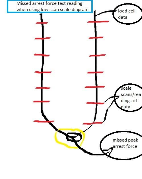
For drop testing, an analog Dillon Dynanometer would be the easiest. this unit could function independently (ie without seperate data acquisition/scale). With a load cell, like USnavy said, you have to have an extremely high scan rate for your scale that interprets your load cell data. THe higher the scan rate (say 1000 plus scans/sec) you jump in price significantly. In the film industry, where they do a lot of 'dropping' of performers etc, they often use analog dynanometers.
THe basic problem with the 'low scan rate' is that even if your load cell is putting out an analog signal (sorry if my terminology is off....i'm not an expert in this stuff),....and your scale/data acquistion is digital (say 100 scans/sec) your drop readings are going to erratic and generally wrong. What happens is the load cell sends out usable data,.... but your scale misses the peak arrest. E.g.: The scale scans a microsecond before the peak and then a micro after, but never actually hits the real 'peak' signal sent by the cell. In this scenario you can drop a hundred pound sample and get a reading of 5lbs, and try again and get a reading of 85 lbs.
http://www.dillon-force.com/...tuemart&Itemid=1
|
|
|
|
|
JimTitt
Aug 6, 2011, 7:50 AM
Post #25 of 29
(15858 views)
Shortcut
Registered: Aug 7, 2008
Posts: 1002
|
Well yes but!
This is so if you just use the display values which are usually updated in the 15-25Hz range and gives the `peak hold´value but normally one also feeds into a computer where the acquisition rate will be 50 or 100Hz from a cheapo signal conditioner. The software is quite capable of creating a force curve from the collected data which will get you very near the true peak, certainly much nearer than most of the other variables that creep in.
Unless you are doing something very complex (and unusual in the climbing gear context) the impact speeds are pretty slow. For example in a standard drop test the force on the top piece varies from minimum to maximum and back over ca 1.5 seconds which gives plenty of time to gather enough data points to establish a very exact curve, much more exact than ones ability to repeatably tie the knots in the rope for example.
For impact analysis the peak isn´t so important as the way it is achieved and then you need to go to a higher scanning rate so you see all the interesting bumpy bits in the curve, then you go to up to systems which acquire data points very fast, Tekscan for example are running at up to 50 million per second. And then you watch your PC die for a little while!
Jim
|
|
|
|
|
|
|
|
|


 !BhddO9gCGk~$(KGrHqMOKjsEry10Wjk+BLJSHKbOtQ~~_12.jpg